Call: 08045476891
 Send Inquiry
 Send Inquiry
Pneumatic training kit
Price 175000.00 INR/ Piece
MOQ : 1 Piece
Pneumatic training kit Specification
- Length
- 600 mm
- Operate Method
- Manual/Automatic (depending on arrangement)
- Used For
- Educational and industrial pneumatic training applications
- Product Type
- Pneumatic Training Kit
- Width
- 450 mm
- Working Voltage
- 310V
- Warranty
- 1-year
- Size
- standard
- Power Source
- Compressed Air
- Usage
- Bike/Car
- Pressure Capacity
- Up to 7 bar
- Color
- Blue and Metallic Grey
- Material
- Aluminum base with Polycarbonate cover
- Mounting Type
- Table top, Portable Design
- Control Method
- Manual push buttons and solenoid operated valves
- Weight
- Approx. 15 kg
- Panel Type
- Modular panel with labeled components
- Safety Features
- Emergency stop, Overpressure relief
- Display Type
- Analog pressure gauge
- Components Included
- Directional control valves, Pneumatic cylinders, Flow control valves, Pressure gauge, Air tubing, FRL unit
- Operating Environment
- Indoor, Dry, Dust-free
About Pneumatic training kit
A brief introduction of the Pneumaticsystem employed in the Training Kit
This Pneumatic Training Kit has beendesigned to provide a firsthand knowledge of how a pneumatic system works. Inrecent times there has been wide spread usage of pneumatic systems for havingvarious types of automated movements to accomplish a job. As such automationhas become an integral part of pneumatic systems. Pneumatic systems are mostlyused for achieving automated movements whereas hydraulic systems are employed mainlyto handle large loads.
In our system there are two Cylindersnamely A which is single acting and B which is double acting. These Cylindersare activated with high pressure air supplied by a Compressor and fed through aFRL. The FRL is a combination of a Filter,used to eliminate the ingress of dust particles to the system and a Regulatorto control and adjust the pressure ofair to the system and a Lubricator to provide necessary lubrication to the pneumaticcomponents to minimize wear and tear. This high pressure air when entersthe bottom or top port of a doubleacting Cylinder an upward or a downward thrust is created resulting in upward or downward movement ofthe plunger respectively. In single acting cylinder there is only inlet portand the upward piston movement is achieved by the thrust created by incominghigh pressure air and the downward movement of the piston is achieved by thepull of gravity when the upward thrust is withdrawn by cutting of the airsupply.
In the pneumatic circuit SV1 isthe mother solenoid valve (2/2) providing supplies to all the destinations.This is a simple on and off valve resuming or cutting off air suppliesdepending on whether the solenoid coil is energized or not.
SV2 is a 3/2 solenoid valveproviding pressurized air to Cylinder A when the solenoid coil isenergized causing upward movement of thecylinder plunger and dumps the cylinder air to the atmosphere when the solenoidcoil is de-energized resulting indownward movement of the plunger due to the action of gravity.
SV3 and SV4 are2/2 solenoid valves as SV1 and supplies pressurized air to the TwoPressure Valve. Two Pressure Valve has been used to apply simple logic tofacilitate automatic control. When both the inlets of Two Pressure Valve aresupplied with high pressure air an output of pressurized air is available atthe outlet port of the valve which is then applied at the pilot port of a 5/2Pilot operated Pneumatic valve. However, if any of the two inputs to the Two Pressurevalve is withdrawn the valve will fail to provide an output. The pilot operatedpneumatic valve causes downward movement of the plunger of double acting CylinderB when there is no pilot pressure and causes a reversal of direction resultingin upward movement of the plunger of Cylinder B when a pressure is applied atthe pilot port of the valve. When both SV3 and SV4solenoid valves are energized upward movement of the plunger of cylinder B isachieved. When any of these two solenoid valves namely SV3 and SV4is de-energized the pilot operated 5/2 pneumatic valve should causereversal of plunger movement of Cylinder B. However, despite withdrawal ofsupply of air from Two Pressure Valve there will remain some residual pressurein the pilot line preventing any such reversal of direction. Hence, asolenoidvalve SV5 has been introduced to release the residual pressure. SV5is a 3/2 solenoid valve like SV2. When SV5 is on itconducts available high pressure air to the pilot port of the Pilot operatedPneumatic Valve and when SV5 is off, it relieves residualpressure of the pilot line to the atmosphere. SV5 is switchedon when both SV3 and SV4 are on causing upward movementof the plunger of cylinder B andSV5 is switched off whenany of SV3 and SV4 is switched off causing reversal ofdirection as already stated. The solenoid valves get actuated by the operationsof limit switches fitted with Cylinder A and Cylinder B. These limit switchesare pressed on and off by the movements of the plungers of both the Cylinders.
Besides above a quick release valvehas been provided with the single acting Cylinder to achieve fast downwardmovement of the plunger of the Cylinder A.
There are three types of automated movementsunder the category of Option 1, Option 2 and Option 3 which have been explainedin detail in the following pages.
Comprehensive Training Solution
This kit is engineered to provide hands-on experience in pneumatic systems for both educational institutions and industrial training centers across India. Modular design and clear labeling make it easy for users to identify and understand various components, enhancing learning outcomes. The tabletop form factor and portable construction allow training anywhere indoors, provided the environment is dry and dust-free.
Versatile Components for Realistic Simulations
Featuring high-quality components such as directional and flow control valves, pneumatic cylinders, pressure gauges, and FRL units, the kit replicates actual industrial pneumatic systems. These elements, combined with manual or solenoid-based operation and an analog pressure display, ensure realistic demonstrations and practical skill development for automotive and mechanical applications.
FAQ's of Pneumatic training kit:
Q: How do I set up the pneumatic training kit for use?
A: To set up the kit, position it on a stable table indoors (in a dry, dust-free environment). Connect the compressed air supply to the FRL unit, and ensure all air tubing is securely attached to the labeled panel ports. Check the control methods required-either manual push buttons or solenoid-operated valves-before powering on the system.Q: What are the main benefits of using this pneumatic training kit?
A: The kit offers practical, hands-on learning about pneumatic circuits and components, enabling users to understand real-world engineering applications. Its portability, modular panel design, and inclusion of industry-standard parts add significant educational value, and built-in safety features ensure user protection during operation.Q: When should the emergency stop and overpressure relief features be used?
A: The emergency stop should be activated immediately if any unsafe condition or malfunction occurs during operation. The overpressure relief will automatically protect the system if pressure exceeds safe levels, but regular monitoring using the analog pressure gauge is recommended.Q: Where can this training kit be effectively used?
A: It is best suited for indoor environments, such as technical classrooms, industrial training labs, and workshop settings. Ensure the location is dry and free of dust for optimal performance and longevity.Q: What is the process for switching between manual and automatic control modes?
A: Switching control modes depends on the planned experiment or demonstration. For manual operation, use the push buttons provided; for automatic or programmable control, employ the solenoid-operated valves as per instructions. Always refer to the included user manual for detailed steps.Q: Who is the manufacturer and what after-sales support is available?
A: This kit is produced by a certified manufacturer, service provider, and supplier based in India. It comes with a 1-year warranty, and technical assistance or servicing can be arranged by contacting the supplier directly.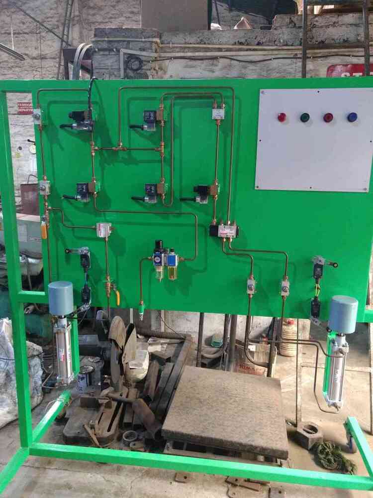
Tell us about your requirement

Price:
Quantity
Select Unit
- 50
- 100
- 200
- 250
- 500
- 1000+
Additional detail
Mobile number
Email

Contact Details
D. G. T. Engineers Pvt. Ltd.
GST : 19AABCD6670R1ZW
- 44/11, Mall Road, Dum,Kolkata - 700080, West Bengal, India
- Phone :08045476891
Developed and Managed by Infocom Network Private Limited.
